
For your electrician
Wiring guide for electricians
First-fix electrical guidance for motorised shaped gable and rectangular blinds. Share this page with your electrician so the cabling is provided correctly during the build. If anything is unclear, talk to us before work starts and we will give you specific instructions for your installation.
Section 1: Mains voltage (240V AC intelligent motors)
This section applies to larger shaped gable blinds powered by 240V Somfy Sonesse intelligent motors.
Motor specification
240V AC intelligent motors with an integrated wireless receiver.
Wiring requirement
Each motor requires a dedicated connection via a flex outlet plate positioned at the base of each slope. The outlet plate must accommodate the blind's headrail, which measures approximately 80mm in width.
Connection details
Extend wiring from the flex outlet to a fused switched spur located at a more accessible, lower level. This configuration is essential for individual blind control and safety. Our team will install the blind and connect the motor cable to the mains supply provided.
Do not shorten the motor cable. The motor cable also acts as an aerial for receipt of the wireless control signal. Shortening it will reduce or eliminate wireless range.
Safety and control
Incorporate a 5 amp fuse for each blind within the switched spur to safeguard the motor. The setup must allow each blind motor to be isolated independently for maintenance or troubleshooting.
Section 2: Low voltage (DC intelligent motors)
This section applies to shaped gable blinds and rectangular free-hanging blinds powered by low-voltage DC motors. These motors require less complex wiring than mains-voltage installations.
Motor specification
12V, 18V or 24V DC motors, depending on the type and size of blind specified. The exact voltage will be confirmed by our team during the planning stage.
Cable installation
- 1
Run a 0.75mm twin flex cable from the cable exit point of each blind position, leaving a tail of approximately 500mm. For rectangular blinds, the cable exit is at the top right-hand corner of the window opening (viewed from inside the room). For shaped gable blinds, the cable exit is where the bottom of the sloped section meets the vertical section of the window. The cable should emerge as far back into the window recess as possible, at the junction where the window frame meets the plasterboard. See the drawing below.
This must be 0.75mm flexible twin cable. Do not install grey twin and earth or any other rigid cable. The flex needs to connect directly to the blind motor and must be pliable enough to route through the headrail.
Cable routing
- 2
At the blind end, the twin flex should exit the wall at the junction where the window frame meets the interior plastered reveal. Route all cables back to a single designated termination point, for example a cupboard, loft space or utility area.
Maximum cable run: 25 metres. The total length of the 0.75mm twin flex from blind to termination point must not exceed 25 metres, to prevent voltage drop. If any run exceeds this, please consult our team.
Cable labelling
- 3
Label every cable at both ends with the window reference, for example W1, W2, D7 Left. Multiple cables will arrive at the termination point and must be individually identifiable. Without labelling, commissioning becomes significantly more difficult.
Termination point
- 4
Leave approximately 500mm of cable at the termination point for connection to the transformer. The transformer converts mains voltage to regulated DC and can power up to five motors from a single unit. Our team will supply and install the transformer.
Power supply
- 5
Install a standard 13 amp socket or fused switched spur at the termination point to power the transformer. For installations with more than five blinds, two sockets may be required, one per transformer.
Drawing: cable exit position (low voltage DC)
The diagram shows the correct cable exit position for low-voltage DC motors. The cable should emerge at the top right-hand corner of the window opening (interior view), at the junction where the window frame meets the plastered reveal.
Additional notes
Architect's drawings show external elevations. The correct cable exit positions correspond to the right-hand side of each window when viewed from inside the property. Take care not to mirror the drawing.
- Maintain the maximum cable run length of 25 metres for the 0.75mm twin flex to avoid voltage drop.
- All installations must comply with the latest electrical safety standards and regulations (BS 7671).
- Coordination with our team for final setup and operational testing is essential to ensure the blind systems work correctly.
This document is a guidance note. Installations can and do vary. Please consult the SSC team for specific instructions for your installation before commencing work.
Wiring Guide V5. Last updated March 2026.
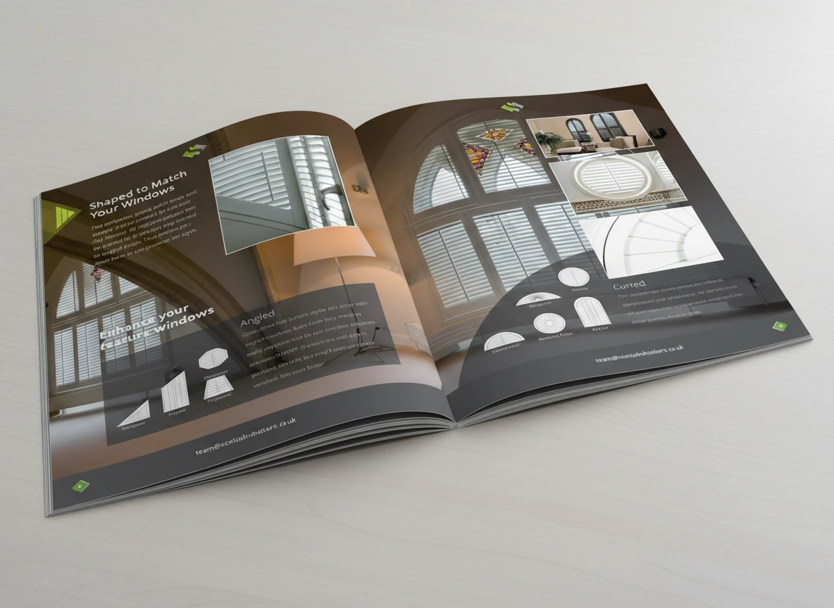
Start with our brochure
52 pages of ideas, product details, and real installations from homes across Scotland. Request your copy and take the first step.